35MHz/65MHz/100MHz Arbitrary Waveform Generator, 2-CH
Overview
With frequencies up to 100 MHz, 16Bit Resolution, and arbitrary waveforms of up to 16 Mpts, the TFG6800 series products can reproduce any waveform with high quality. The new portable design and optional power amplifier make this one of the most flexible and popular generators on the market. It can be used in various applications, such as testing electronic circuits, generating signals for scientific experiments, and simulating real-world signals.
Product Model
TFG6803/TFG6806/TFG6810
The TFG6800 series 35MHz/65MHz/100MHz signal generators are multifunctional generators that combine multiple functions, including function generator, arbitrary waveform generator, pulse generator, harmonic generator, analog/digital modulator and counter. All three models have two channels with fully equivalent functions and precisely adjustable phases, making them true dual-channel signal generators.
This series of 35/65/100 MHz Function Signal Generator could be widely used in areas of Education, R&D, Industrial&Electrical Production and Test.
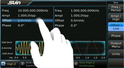
1. 7 inch touchscreen display for a easier operation
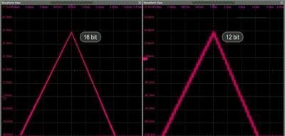
2. 16bit vertical resolution to produce a higher quality waveform.
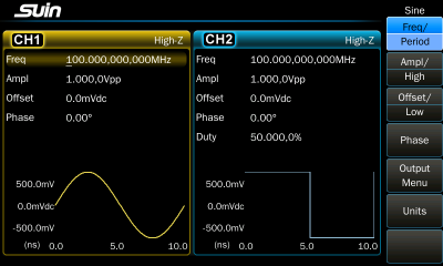
3. Sine and Square have same characteristics.
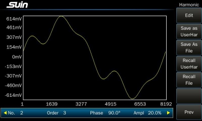
4. Harmonics function gives you the ability to add higher-order elements to your signal.
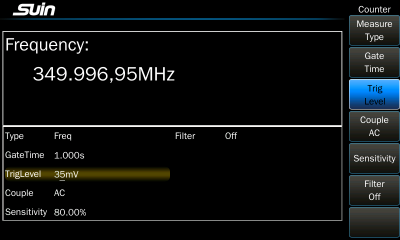
5. 8-digit hardware frequency counter with statistics function and input range of 1mHz – 350MHz.
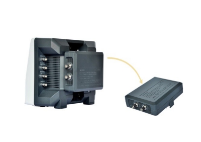
6. Removable power amplifier option makes it easy to install and uninstall.
An Arbitrary Waveform Generator (AWG) is a sophisticated piece of electronic test equipment that can create a wide range of electrical waveforms. These devices are essential in the fields of electronics and communication for testing, design, and research.
Key Features of an AWG:
Waveform Flexibility: Ability to generate any waveform, whether periodic or non-periodic, by defining the waveform points.
Frequency Range: Capable of generating signals over a wide frequency range, often from very low frequencies (Hz) to hundreds of MHz or even GHz.
Amplitude Control: Precise control over the amplitude of the generated waveform.
Phase Control: Capability to adjust the phase of the waveform.
Sample Rate: High sample rates, allowing for high-resolution waveform creation.
Memory Depth: Large memory depth to store complex waveforms.
Modulation: Supports various modulation techniques such as AM, FM, PM, and PWM.
Output Channels: Multiple output channels for generating synchronized waveforms.
User Interface: Intuitive user interfaces, often with graphical displays, for waveform design and manipulation.
Connectivity: Interfaces for connecting to PCs and other devices, often including USB, Ethernet, and GPIB for remote control and automation.
Common Uses of an AWG:
Testing and Development:
Component Testing: Used to test electronic components like amplifiers, filters, and ADCs by providing a controlled input signal.
System Testing: Useful in testing the overall performance of electronic systems and circuits.
Communication:
Signal Simulation: Simulating communication signals for testing receivers and transmitters.
Modulation/Demodulation: Testing modulation and demodulation schemes in communication systems.
Research and Development:
Experimental Waveforms: Creating and testing new waveform shapes and patterns in research settings.
Signal Processing: Testing signal processing algorithms and systems.
Education and Training:
Laboratory Experiments: Used in educational settings for laboratory experiments and training students in signal generation and analysis.
Medical Equipment:
Bio-Signal Simulation: Generating biological signals (like ECG, EEG) for testing medical devices.
Aerospace and Defense:
Radar and Sonar: Simulating radar and sonar signals for testing and development.
Electronic Warfare: Generating complex waveforms for electronic warfare testing and simulation.
AWG Example Specifications:
Waveform Types: Sine, square, triangle, ramp, pulse, noise, and arbitrary.
Frequency Range: Typically from DC to several GHz.
Sample Rate: Up to several GSa/s (gigasamples per second).
Amplitude Range: Often from a few millivolts to several volts.
Memory Depth: Can range from a few thousand points to several million points.
How AWG Works:
An AWG creates waveforms by using digital-to-analog converters (DACs) to convert digital data into an analog signal. The waveform is defined by a series of data points stored in the AWG's memory, which the DAC reads out at a specified sample rate. This process allows for the generation of very precise and complex waveforms.
SUIN is a high-tech company specializing in the R&D, production, testing, sales, and service of test and measurement instruments, electrical products, and application software. With a robust foundation and advanced SMT production line, SUIN achieves an annual capacity of 30,000 sets of digital electronic instruments. Key products include signal generators, digital multimeters (DMM), spectrum analyzers, frequency counters, power quality analyzers, and programmable DC power supplies, all of which are well-received in both domestic and international markets. The company holds several certifications, including ISO9001 and various CE EMC and LVD certificates for its product lines, ensuring high quality and compliance with industry standards.
Questions & Answer
From TFG6810 Arbitrary Waveform Generator-100MHz, 2CH
Q: What is the bandwidth of the Suin TFG6810? How many channels does it have?
A: The Suin TFG6810 is a 100 MHz, 2 channel arbitrary waveform generator.
Q: What is the sample rate for TFG6810?
A: The sample rate for the TFG6810 is 250 MSa/s.
Q: Does the TFG6810 have a higher oscillator?
A: Yes, optional oscillator with 1ppm stability could be configured if users have a higher measurement demand.
Q:What’s the rise/fall time of Square for TFG6810?
A: It’s ≤4.2ns.
| TFG6803 | TFG6806 | TFG6810 | ||
Frequency | ||||
| Sine/Square | 1μHz-35MHz | 1μHz-65MHz | 1μHz-100MHz | |
| Pulse | 1μHz-25MHz | |||
| Ramp | 1μHz-3MHz | |||
| PRBS | 1kbps~60Mbps | |||
| Noise (-3dB) | 100MHz Width | |||
| Other | 1μHz~20MHz | |||
| Resolution | 1μHz or 12 digits | |||
| Accuracy | ±(20ppm + 14pHz) | |||
Waveform | ||||
| Type | 165 kinds include: Sine, Square, Ramp, Pulse, Noise, DC, PRBS, user-defined,Arbitrary waveform, user-defined harmonic, etc | |||
| Sample rate | 250MSa/s | |||
Vertical resolution | 16 bits | |||
| Arbitrary | Sample Rate | 1μSa/s~125MSa/s | ||
| Length | 2-16Mpts | |||
| Resolution | 16 bits | |||
| Square | Rise/Fall Time | ≤4.2ns | ||
| Duty Cycle | 0.0001%~99.9999% | |||
| Pulse | Rise/Fall Time | ≥8ns | ||
| Width | 13ns ~ (period - 13ns) | |||
Amplitude(High Z) | ||||
| Range | 2mVpp~20Vpp, frequency≤10MHz 2mVpp~10Vpp, frequency>10MHz | |||
| Resolution | 1mVpp or 4digits | |||
| Accuracy | ±(of settings value×1%+1mV), Sine 1kHz, ≥10mVpp, offset 0V | |||
Offset(High Z) | ||||
| Range | ±10Vpk(ac+dc) | |||
| Resolution | 1mVdc | |||
| Accuracy | ±(|setting value|×1%+2mV+amplitude value ×0.5%) | |||
Sweep | ||||
| Range | 1μHz ~ upper frequency limit | |||
| Type | Linear, logarithmic | |||
| Time | 1ms to 500s | |||
Modulation | ||||
FM,AM,PM, PWM, Sum | Carrier Waveform | Sine, Square, Ramp (only pulse for PWM), etc. | ||
Modulating Waveform | Sine, Square, Ramp, etc. | |||
| Modulating Frequency | 1mHz to 100kHz | |||
FSK,4FSK, NFSK,PSK, 4PSK,NPSK, ASK,OSK | Carrier Waveform | Sine, Square, Ramp, ect | ||
Hop Frequency | 1μHz -upper limits | |||
| Hop Rate | 1mHz to 1MHz | |||
Burst | ||||
| Mode | Triggered, Gated | |||
| Period | 1μs to 600s | |||
| Count | 1 to 100000000 cycles | |||
Counter | ||||
| Frequency Range | 1mHz to 350MHz(DC Couple) 10Hz to 350MHz(AC Couple) | |||
| Resolution | 8 digits/s | |||
Period and Pulse Width Measurement | 100ns to 20s | |||
| Duty Cycle Measurement | 0.1% to 99.9% | |||
General Characteristic | ||||
| Power | AC 100~240V, 50/60Hz ±10% | |||
| AC 100~120V, 400Hz ±10% | ||||
| Dimension & Weight | 226mm×200mm×125mm, Approx. 2.9kg | |||
226mm×200mm×166mm, Approx. 3.3kg (if amplifier power is selected) | ||||
Power Cord:1pcs
BNC cable:1pcs
CD(software+manual):1pcs
TCXO(Temperature Compensated Crystal Osillator):±1ppm accuracy,±1ppm/year aging rate
Power Amplifer:2 times power amplifer,Max output power 8W(8Ω)
IOT interface:Based on LoRa